A brake is not an accessory on a professional dynamometer. It determines how well your shop can hold RPM, reproduce a road-load condition, tune safely under sustained power, and move from one vehicle to the next without losing valuable test time. In the eddy current versus water brake decision, the right answer depends less on peak horsepower marketing and more on the work your facility performs every day.
For most chassis dynamometer installations serving performance tuning, diagnostics, and motorsport preparation, an eddy current brake provides the control response and operational flexibility that matter most. Water brakes remain highly capable absorbers, particularly in dedicated engine-cell and constant-load applications. The difference is in how each system creates load and how that behavior affects your testing workflow.
Eddy Current Versus Water Brake: The Core Difference
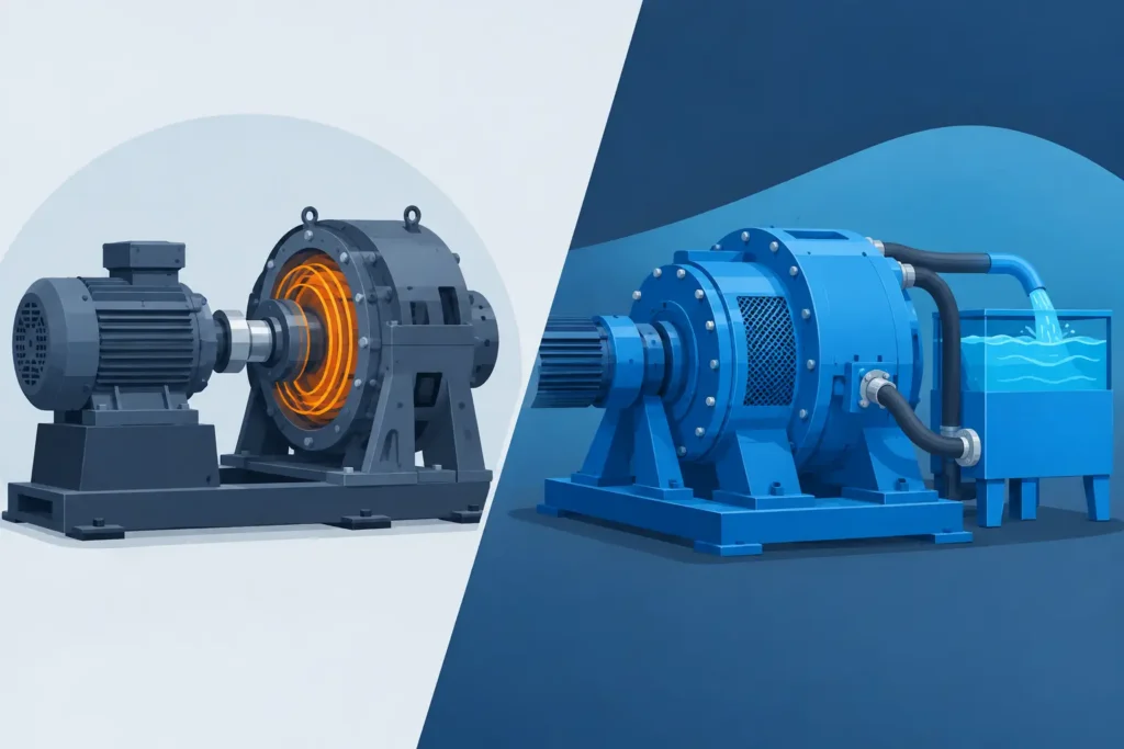
An eddy current brake creates resistance through electromagnetism. When electrical current energizes coils around a rotating steel rotor, it induces eddy currents in the rotor material. Those currents create a magnetic field that opposes rotation, converting vehicle power into heat. There is no friction material pressing against the rotor and no mechanical contact inside the brake.
A water brake, also called a hydraulic dynamometer or water absorber, generates load by accelerating and shearing water inside a rotor-stator chamber. The rotor transfers energy into the water, which is then discharged or recirculated through a cooling system. It is a proven, heavy-duty method of absorbing large amounts of power for extended periods.
Both systems can apply repeatable load. But their response characteristics, installation requirements, service demands, and best-fit applications are different enough that a buyer should evaluate the complete test environment before choosing a brake type.
Why Eddy Current Brakes Fit Modern Chassis Dynos
A chassis dyno has to work with a complete vehicle, not an isolated engine. Tire behavior, roller inertia, drivetrain losses, gear selection, traction, cooling airflow, and vehicle safety all affect the test. The brake system must react quickly while software manages the run.
Eddy current brakes are especially effective here because braking torque can be adjusted electronically and rapidly. The dyno control system can command a load change based on RPM, roller speed, throttle position, target acceleration rate, or a programmed road-load curve. That makes steady-state calibration, part-throttle mapping, boost control work, and diagnostic testing practical on the same platform.
For a tuner, this means the dyno can hold a specific engine speed while fuel, ignition, boost, cam timing, or torque management is adjusted. For a race-prep shop, it means simulating acceleration through a gear or loading the vehicle at a critical RPM point. For a technical school or diagnostic center, it means demonstrating controlled operating conditions instead of relying only on a wide-open-throttle inertia pull.
Eddy current braking also supports a clean installation. It requires electrical power and effective cooling airflow, but it does not require a continuous high-volume water supply, water-treatment plan, drain capacity, or a process-water cooling circuit. That reduces infrastructure complexity for many existing workshops.
What Eddy Current Brakes Do Best
Eddy current systems are strong where fast, controlled, repeatable vehicle testing is the priority. They are typically the practical choice for:
- Steady-state ECU calibration and live diagnostics
- Controlled acceleration tests and road-load simulation
- Repeatable power verification for performance vehicles
- 2WD and synchronized 4WD chassis dyno applications
- Shops that need braking capability without water infrastructure
The main engineering limitation is that eddy current brake torque is speed-dependent. Braking force is strongest once the rotor is turning at useful speed and falls as speed approaches zero. This is rarely a problem during normal chassis dyno testing, but it matters when a test requires very high torque absorption at extremely low roller speed.
Heat management also remains critical. The brake absorbs energy, and that energy becomes heat. A properly engineered dyno needs sufficient brake capacity, cooling airflow, thermal protection, and control logic for the intended duty cycle. A short power run and a repeated full-load endurance session are not the same job.
Where Water Brakes Make Sense
Water brakes have earned their reputation in demanding engine development and industrial testing. Their strength is sustained energy absorption. With the right water supply and cooling capacity, a water brake can absorb substantial power continuously and operate for long, severe test cycles.
This makes them a natural fit for dedicated engine dynamometers, marine engines, agricultural power units, and test cells where an engine is coupled directly to the absorber. In those environments, water plumbing, heat rejection equipment, drainage, and process controls are already part of the facility design.
A water brake can also produce substantial torque at lower speeds than an eddy current brake, depending on its configuration and operating conditions. That characteristic can be valuable for engine lugging tests, durability runs, and applications centered on long steady-state operation at heavy load.
The trade-off is operational infrastructure. Water quality matters. Flow must be stable, inlet pressure must be controlled, and outlet temperature must stay within safe limits. The facility may need supply piping, filtration, valves, pressure monitoring, drains, cooling towers, or a closed-loop heat exchanger. In cold climates, freeze protection and winter shutdown procedures add another layer of planning.
For a chassis dyno shop, that complexity is not always justified. Water brakes can be integrated into vehicle dynamometer systems, but they are less common when the goal is flexible tuning and rapid daily throughput rather than fixed-cell endurance testing.
Brake System Comparison for Professional Buyers
| Factor | Eddy Current Brake | Water Brake | |---|---|---| | Load generation | Electromagnetic resistance | Hydraulic water shear | | Control response | Fast electronic adjustment | Effective but dependent on water-flow control | | Low-speed absorption | Reduced torque at very low speed | Strong capability in suitable configurations | | Continuous heavy-load work | Strong when correctly sized and cooled | Excellent with adequate water and heat rejection | | Facility requirements | Electrical supply and ventilation | Water supply, plumbing, drainage, cooling, and controls | | Service considerations | Inspect electrical and cooling components | Manage water quality, seals, plumbing, and corrosion risk | | Typical best fit | Chassis dynos, tuning, diagnostics, transient testing | Engine cells, endurance testing, industrial applications |
The table does not make one technology universally better. It shows why the application should lead the specification. A brake that is ideal for an engine durability cell can be unnecessarily complicated for a high-volume tuning workshop. Conversely, a compact eddy current chassis dyno should not be specified for a duty cycle that truly requires continuous industrial-scale heat absorption.
Matching Brake Capacity to Your Actual Work
Do not select a brake by advertised horsepower alone. Peak engine power, wheel power, vehicle mass, gear ratio, target test duration, ambient temperature, and test repetition all influence the required system capacity.
A 1,000 hp vehicle making a brief acceleration run presents a different thermal load than a 600 hp vehicle held at high output for several minutes. Likewise, a heavy truck, PTO-driven machine, or high-torque diesel can require substantial braking force even when peak horsepower is not extreme. The usable specification is the combination of braking torque, speed range, continuous absorption capacity, roller mass, axle capacity, and cooling design.
For 4WD chassis testing, synchronization is equally important. Front and rear roller groups must remain accurately matched as the brakes apply load. Poor synchronization can create driveline windup, unstable readings, tire scrub, and avoidable stress on AWD and 4WD systems. A fully synchronized platform with properly controlled eddy current braking gives the operator a stable foundation for serious calibration work.
Control software deserves the same scrutiny as the hardware. The operator should be able to define load curves, set acceleration rates, establish safety limits, log repeatable data, and stop the run quickly if temperatures, speed, or synchronization move outside limits. Brake capability without precise control is not a professional testing solution.
The Practical Decision for Tuning Shops
If your business earns revenue through ECU calibration, performance verification, diagnostic work, and race-car preparation, an eddy current chassis dynamometer is usually the stronger investment. It supports the controlled, repeatable tests that customers expect while keeping installation and daily operation straightforward. Dynomax braked systems are designed around this reality: serious loading capability, synchronized 4WD operation, and practical control for shops that need to test more vehicles with confidence.
Choose a water brake when your operation is built around dedicated, sustained-load testing and has the water, cooling, and facility infrastructure to support it. That may be the correct decision for an engine development cell or an industrial endurance program. It is not automatically the best choice simply because it can absorb large power numbers.
The most productive dyno is the one that matches your vehicles, your test cycles, and your shop workflow. Specify the brake around the work you need to perform next week, not only the biggest horsepower figure you may see once a year.